2000-12000mm Długość zakresu surowca 3D Maszyna do wiercenia wiązki kanałowej 11KW Moc silnika wrotnika
Cel linii produkcyjnej:
Ta linia produkcyjna jest przede wszystkim zaprojektowana do wykonywania wierceń, znakowania,), ), ), ), ), ), ), ), ), ), ), ), ), ), ), ), ), ), ), ), ), ), ), ), ), ), ), ), ), ), ), ), ), ), ), ), ), ), ), ), ), ), ), ), ), ), ), ), ), ), ), ), ), ), ), ), ), ), ), ), ), ), ), ), ), ), ), ), ), ), ), ), ), ), ), ), ), ), ), ), ), ), ), ), ), ), ), ), ), ), ), ), ), ), ), ), ), ), ), ), ), ), ), ), ), ), ), ), ), ), ), ), ), ), ), ), ), ), ), ), ), ), ), ), ), ), ), Jest specjalnie zaprojektowany do wykonywania tych podstawowych zadań przetwarzania z wysoką precyzją,zapewnienie zgodności gotowej stali z rygorystycznymi normami wymiarowymi i konstrukcyjnymi wymaganymi w zastosowaniach przemysłowych.
GłównySspecyfikacje:
| Parametry |
Wartość |
| Rozmiar obróbki |
Zakres szerokości |
150 ̊1250 mm |
| Zakres wysokości |
100 ‰ 600 mm |
| Zakres długości surowca |
2000 ∼ 12000 mm |
| Zakres długości gotowego obrabiarkę |
2000 ∼ 12000 mm |
| Węgiel wiertniczy |
Liczba wrotów wiertniczych |
3 |
| Węzeł spindlowy |
BT1pozycja |
| Moc silnika wrotnika |
11 kW |
| Prędkość obrotu |
200~3000 obrotów/min |
| Zakres średnicy wiercenia |
φ5~φ30 |
| Oś CNC |
Moc serwomotora osi X |
Około 4,4 kW. |
| Maksymalna prędkość w osi X |
40 m/min |
| Moc serwomotora do wiercenia w osi pozycji poziomej |
Około 1,5 kW. |
| Maksymalna prędkość wiązki poziomego ustawienia wiertniczej |
10 m/min |
| Siła serwomotora wiązki wiertniczej wiertniczej |
Około 2 kW |
| Maksymalna prędkość wiązki poziomego ustawienia wiertniczej |
10 m/min |
| Siła serwomotora o pionowej osi pozycjonowania wiercenia |
Około 3 kW. |
| Maksymalna prędkość wiązki pozycjonowania pionowego wiertarki |
10 m/min |
| Siła serwomotora o pionowej osi zasilającej wiertarki |
Około 3 kW. |
| Maksymalna prędkość wiercenia pionowej osi zasilającej |
10 m/min |
| Czasopismo narzędziowe |
Ilość |
3 zestawy |
| Rodzaj |
rodzaj w linii |
| Ilość narzędzia |
4 x 3 |
| Jednostka oznaczania hydraulicznego |
Ilość znaków |
36 |
| Wielkość znaku |
Φ10 |

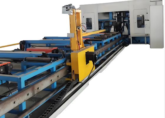
1. Trójwymiarowy wózek do wiercenia
Komponent ten składa się z biegów, serwomotorów i manipulatorów.i jest zdolny do automatycznego podnoszenia i opuszczania zgodnie ze specyfikacjami profilu,Po zacisnięciu obrabialnika obrabialnia jest napędzana przez serwomotor.kawałek roboczy jest podawany w kierunku X, skutecznie zapewniając dokładność obróbki wzdłużnej operacji wiercenia.
2. Trójwymiarowy hosta wiertniczy
Głównie składa się ona z podstawy, łóżka, ruchomego suwaków, skrzynki wrzutowej, urządzenia do tłoczenia górnego, urządzenia do zaciskania bocznego oraz magazynu narzędzi typu rzędowego.Łóżko wykazuje doskonałą sztywność i stabilność, dzięki czemu jest odporny na obciążenie i wibracje powodowane podczas szybkiego obróbki.Ta wydajność konstrukcyjna skutecznie zapewnia dokładność obróbki obrabiarki podczas ciągłej pracy.
2. Trójwymiarowa instalacja wiertnicza (konfiguracja skrzynki szpilkowej)
Głowica wiertnicza jest wyposażona w trzy skrzynki wiertnicze, a mianowicie skrzynkę wiertniczą z stałą stroną, skrzynkę wiertniczą z ruchomą stroną i skrzynkę wiertniczą z górną jednostką,które są stosowane odpowiednio do wiercenia poziomego i pionowegoKażda skrzynka z wrotami może działać niezależnie lub wykonywać operacje wiertnicze jednocześnie.Każde pudełko z wrotami jest wyposażone w zestaw szybkich wrotów mechanicznych BT40; odpowiedni magazyn narzędzi typu rzędowego może pomieścić do 4 wiertarek o różnej średnicy (jeśli narzędzie nie jest zamontowane na wrzecie),umożliwiające automatyczne obróbki 4 różnych średnic otworów w jednym cyklu zaciskania obróbki.
Trzy urządzenia z pudełkiem z wrotami są zamontowane na boku łóżka. Each spindle box unit is driven by two sets of servo motors to realize the horizontal and vertical movement of the spindle box—this movement is powered by a ball screw and guided by a precision linear rolling guideW trakcie procesu wiercenia urządzenie to stosuje siłę nacisku na przedmiot w dwóch kierunkach.Mechanizm tłoczenia napędzany cylindrem jest umieszczony nad przedmiotem do pracy, aby nacisnąć przedmiot do horyzontalnych walców nośnychDodatkowo na boku zainstalowany jest mechanizm tłoczenia z napędem cylindrowym, który stosuje siłę tłoczenia bocznego do przedmiotu, skutecznie zabezpieczając przedmiot podczas obróbki.
Na przykład podczas próbnych sesji demonstracyjnych, the machine tool can effectively demonstrate its machining capabilities through standard H-beam samples (with varying flange widths and web thicknesses) and channel steel samples of different dimensionsWyświetlane przykłady wyraźnie ilustrują zdolność narzędzia maszynowego do dokonania dokładnego ustawienia otworu, płynnych nitek,i wyraźnych wzorów oznakowania, które w pełni odzwierciedlają jego wysoką precyzję i niezawodność w praktycznych scenariuszach zastosowań.
Maszyna wiertnicza CNC H Beam High Speed jest wykorzystywana głównie w warsztatach konstrukcji stalowych i projektach budowy mostów.wykonuje precyzyjne obróbki drogowe wiązek H stosowanych do ram i konstrukcji nośnychW przypadku scenariuszy budowy mostów, w przypadku których konstrukcja mostów jest nieprzewidywalna, w przypadku których konstrukcja mostów jest nieprzewidywalna, w przypadku gdy konstrukcja mostów jest nieprzewidywalna, w przypadku gdy konstrukcja mostów jest nieprzewidywalna, w przypadku gdy konstrukcja mostów jest nieprzewidywalna, w przypadku gdy konstrukcja mostów jest nieprzewidywalna, w przypadku gdy konstrukcja mostów jest nieprzewidywalna, w przypadku gdy konstrukcja mostów jest nieprzewidywalna.wykonuje wysokiej dokładności operacje wiercenia na balnach H. To pomaga poprawić integralność konstrukcyjną mostówJego wysoka wydajność operacyjna zapewnia niezawodne wsparcie techniczne dla tych kluczowych sektorów infrastruktury,zapewnienie sprawnego przebiegu realizacji projektu.

 Twoja wiadomość musi mieć od 20 do 3000 znaków!